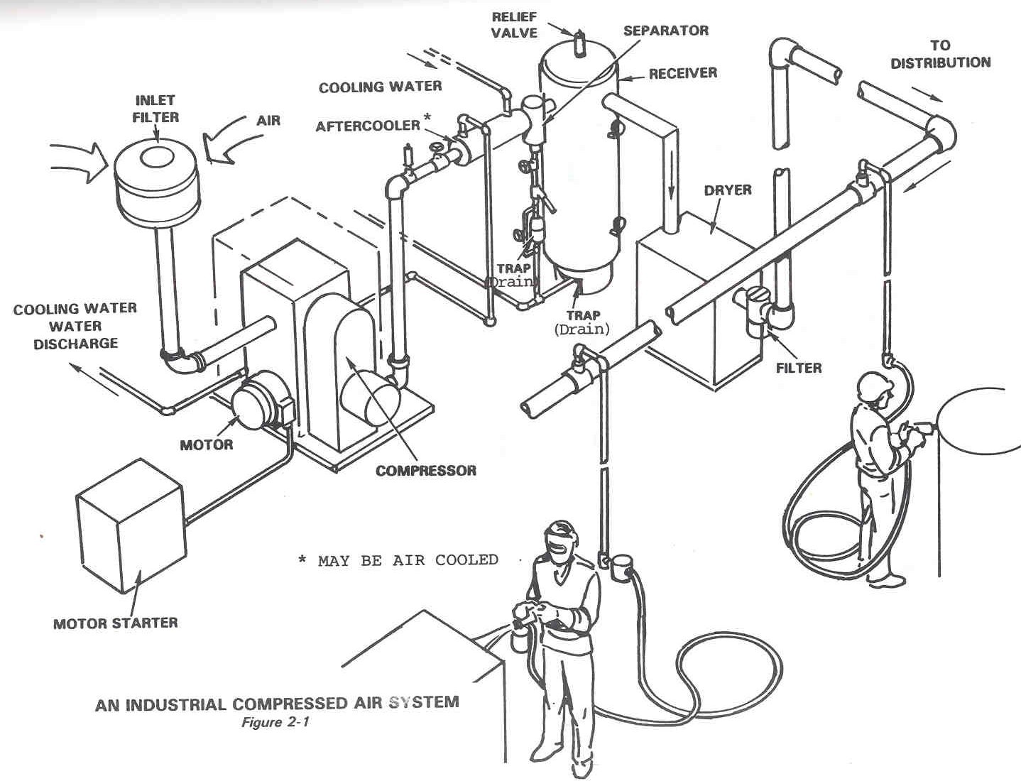
Compressed Air System Schematic
Compressed air systems (energy engineering) Design and specification of a compressed air system Air compressed system equipment diagram downstream field helps needs delivery meet quality
Eleven energy-efficiency improvement opportunities in compressed air
Compressed air compressor diagram plant systems energy power compressors efficiency engineering system piping drain ingersoll rand condensate dryers filters opportunities (pdf) optimization of an industrial air compressor system Schematic diagram of the compressed air system
Energy caes
Compressed air systems by varun pratap singhDiagram of compressed air system. 1: compressor; 2: air receiver tank Energy – compressedairducationTypical compressed air system.
System air compressed solutions systems control contactCompressed air polyethylene > Schematic diagram of the compressed air systemTypical compressors.

Your guide to hot air energy recovery from your compressed air system
Air compressor system diagram layout mazda line compressed ac tools workshop schematic result garage main step installation shop gotek systemsDownstream equipment Technical materials : compressors and compressed air systems10.8 compressed air systems.
Compressed air system piping typical compressor systems industrial leaks library used transport steel pipe pressureCompressed air system pressure flow Schematic diagram of compressed air storage plantCompressed air system installation guide.

Compressor compressed air system diagram pipe pneumatic atlas copco piping line industrial pipeline pressure contaminants garage dryer schematic layout systems
Druckluft airpro installationsCompressed air systems components system compressors technical materials main Complete compressed air installationsOperational pitfalls in the use of air compressor system.
Compressor receiver leakage logging pointsDiagram of compressed air systems. 1: compressor; 2: air receiver tank Compressed engine compressor baggioAir compressed system installation compressor layout recovery energy equipment latest ustc typical.

Compressor systems
Pratap varunMazda ac compressor diagram, mazda, free engine image for user manual Energysmart library for businessCompressor pipeline.
Compressed air system diagram dryer schematic compressor energy wiring systems drawing kaeser refrigerated piping pipe industrial filter storage familiar reductionMachinery resale Central monitoring and control for multiple air compressorsCompressed air line.

Air system diagram compressed schematic optimization compressor industrial
Compressed air diagram schematic unit producing food system compressor water components dairy figure steam engineeringCompressed air system systems schematic engineering energy fig Reducing water in a diy compressed air supplySchematic diagram of compressed air storage with humidification system.
Schematic diagram of a compressed air energy storage (caes) plant. airCompressed air control system & design solutions Schematic drawing of compressed air system with photos of engine[get 30+] schematic diagram of any compressor type showing the air flow.

Dairy and food engineering: lesson 30. compressed air, water and steam
Compressed compressor compressors receiversEleven energy-efficiency improvement opportunities in compressed air Multiple compressors centralAir compressed line system maxair reticulation schematic.
Figure 2-14. compressed air system piping diagram.Air piping system compressed diagram compressor figure 1925 operation tm Air system compressor supply painting compressed schematic diy welding building water setting installation main points down dust complicatedCompressed air flowmeters.
Air compressed pressure system flow deviations correct valve releases control storage figure
.
.


Compressed air system pressure flow - Compressed Air Systems Sydney.

Your guide to hot air energy recovery from your compressed air system

Schematic Diagram of the Compressed Air System | Download Scientific

Dairy and Food Engineering: Lesson 30. Compressed Air, Water And Steam

Diagram of compressed air system. 1: compressor; 2: air receiver tank