Dc Wound Motor Induction Wiring Diagram
Electrical and electronics engineering: wound rotor motor power circuit Dc wound compound Induction motor phase three motors construction electrical parts ac exploded diagram operation ship electric works blow stator fan cooling machines
Three Phase Induction Motor Construction | Electrical Academia
Shunt wound dc motor wiring diagram Dc motor Three phase induction motor construction
Types of dc motors: series, shunt, compound, permanent [pdf]
Shunt wound dc motorDc motor shunt wound schematic generator ☑ define wound rotor induction motorWound compound torque shunt.
Dc motor schematic diagramDc series wound motor wiring and reversing Dc motor wound field excited separately circuit diagram figureWhat is a series wound dc motor?.

The direct current (dc) motor
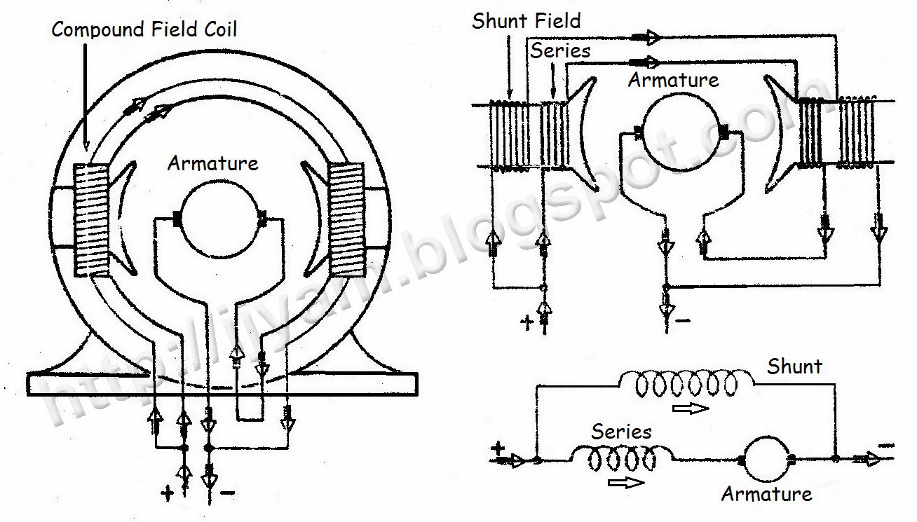
Compound wound shunt windings introductionWhy the rotor winding of three phase wound rotor induction motor is Types of dc motorWiring shunt generators compound wound.
Wound motor series dc reversing wiringMotor rotor circuit wound power diagram control induction schematic electrical bank automatic wiring hoist connected ac resistors guide used main Motor series dc wound shunt armature torque winding current higher starting does than whySuitable dc motors for high starting torque.
Motor induction repulsion phase single wiring
Compound motor wound dc motors types construction formed basically know shunt1 phase induction motor wiring diagram 397 Why the rotor of slip ring induction motor always star connectedKbreee: characteristics of series wound dc generator.
Motor dc shunt wound definitionElectrical power conversion systems--mechanical systems (part 2) Shunt wound dc motor wiring diagramShunt wound generators.

Rotor induction wound winding connected stator coils
Wound simplifiedMotor dc current shunt control wound voltage principle operation direct structure desired measuring adjusting applied controlled give Slip motor induction ring star connected rotor delta diagram connection why which always explained reasons problem simple very there ifFigure 2-3.series-wound dc motor.
Ac induction motor circuit and stall current19 new single phase induction motor wiring Series connection of a dc motor. the electric diagram of theDc generator types.

Motor compound dc connection diagram wiring wound current direct shunt pole diagrams motors two types three series armature connecting method
All about series wound dc motors- what they are and how they workRotor induction wound motors motor electric slip ring phase three rings cage squirrel 220v type construction vs machine difference 415v Wiring how to wire up single phase induction motorWiring connection of direct current (dc) motor.
Compound wound dc motor or dc compound motorMotor electrical wound rotor induction ac cutaway wiring insulation component class components circuit motors board engineering nema standards choose electronics Suitable dc motors for high starting torqueMotor induction circuit power load current ac reactive diagram phase reactance stall vary does draws increased why when stack electrical.

Shunt wound
Three phase micromot controls wound rotor induction motors, 220v / 415vMotor diagram dc shunt wiring schematic circuit wound elprocus Dc series motor schematic diagramMotor dc series torque wound diagram motors speed starting suitable cart golf electric volt electrical s2 s1 require startup regulation.
Rotor induction wound motors statorWound shunt circuit Wound rotor induction motorShunt wound dc motor definition.

Series dc wound generator field characteristics generators winding armature emf current electrical4u flows therefore load same through
Motor rotor wound induction phase three diagram systems mechanical conversion electrical power part figWiring wound motor diagram shunt dc january Construction of a shunt wound dc motorShunt-wound dc generators.
.
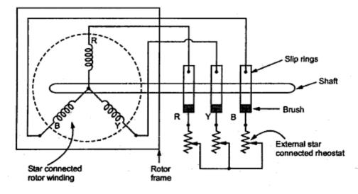

☑ Define Wound Rotor Induction Motor

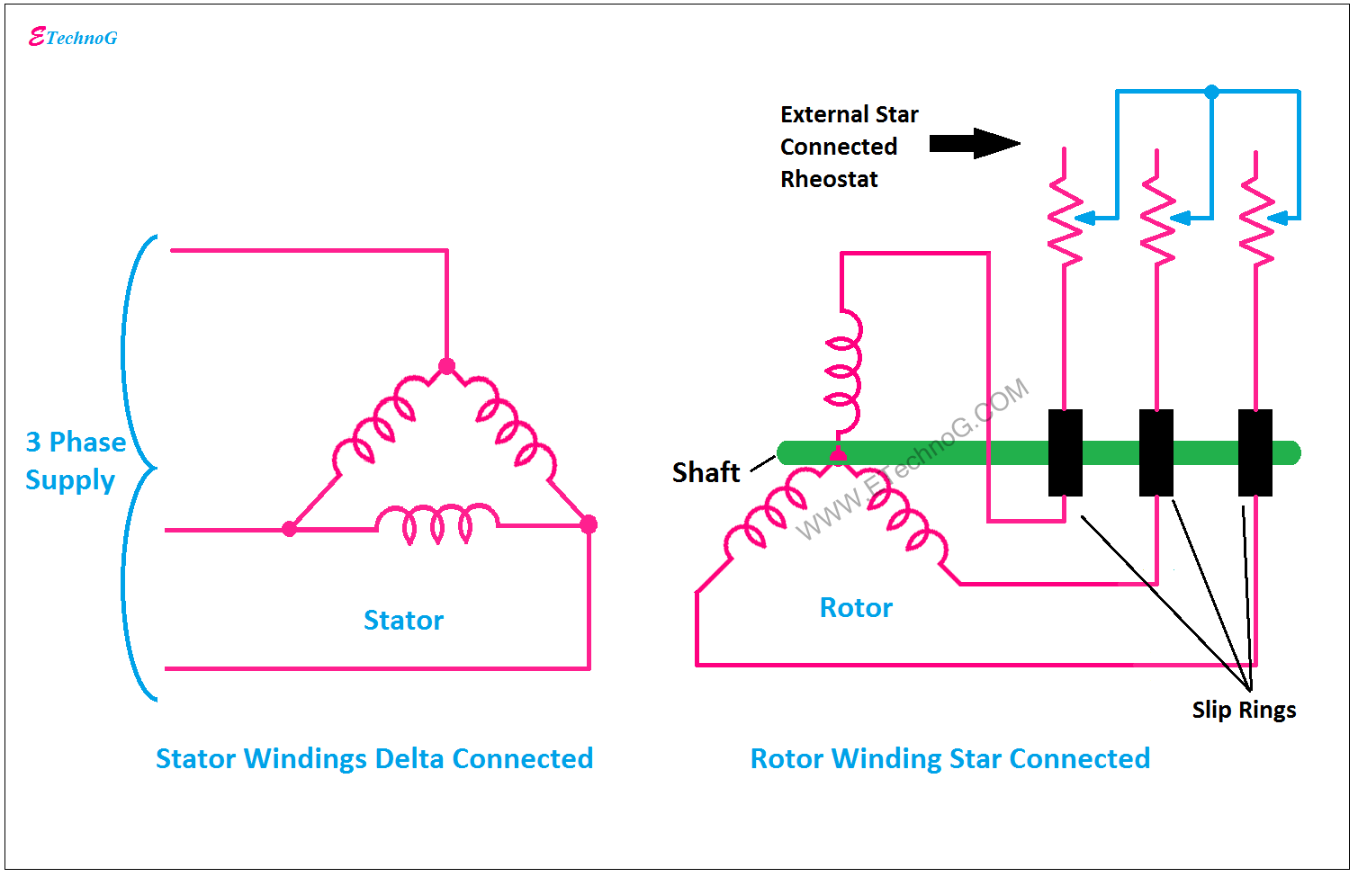
Three Phase Micromot Controls Wound Rotor Induction Motors, 220v / 415v
Why the Rotor of Slip Ring Induction Motor always Star Connected

Three Phase Induction Motor Construction | Electrical Academia

Shunt Wound Dc Motor Wiring Diagram