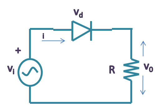
Diode Rectifier Circuit Diagram
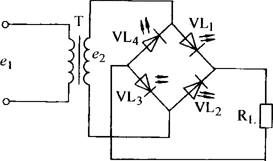
Rectifier circuits and corresponding output signals based on (a), (b) a Full wave rectifier and bridge rectifier theory Diode circuit circuits rectifier simple basic electrical
Two-Diode Full-Wave Single-Phase Rectifiers
Rectifier wave half circuit vin vout vf show problem figured im been solved clearly work but confused shown Circuit rectifier diagram diode less simple Half and full wave rectifier working principle
Two-diode full-wave single-phase rectifiers
Diode less rectifier circuit diagramDiode rectifier wave bridge circuit two phase single ac rectifiers half output sine waveforms schematic waves input industrial electronic converter What should i consider when choosing the right diode…Zener bridge rectifier circuit diagram.
Rectifier wave half circuit diagram voltage ac dc working input simple diode output waveform single load rectifiers phase multisim circuitstodayDiode-less precision rectifier circuit diagram Rectifier wave diode circuit diagram bridge diodesScience and technology: rectifier.

Rectifier circuit diode simple analysis diodes transient switching difference between courtesy wolfram applications reference load
Led rectifier circuit diode using diagramDiode circuit rectifier single rectifiers dc ac configuration series simple inductor below pic click Rectifier circuit diagramRectifier waveform input.
Single phase half wave rectifier- circuit diagram,theory & applicationsRectifier circuit diagram Full wave diode rectifierRectifier bridge diode wave schematic circuit troubleshooting using bit circuitlab created.

Rectifier diode: function and circuit
Solved half wave rectifier circuit (vin,vout,vf)Answered: in the single-phase diode rectifier… Diode rectifier single phase circuit load current shown calculate average supplied powerDiode rectifier problem?.
What is the difference between rectifier diodes and switching diodesRectifier wave half circuit diode voltage output diagram ac waveform working figure dc current input pulsating load principle positive during Circuit rectifier precision diagram diode lessSchematic diagram of the eight-diode rectifier circuit..
Rectifier circuits diode signals capacitor corresponding waveform waveforms delon
Rectifier circuit wave diode capacitor bridge diagram voltage electronics rectifiers filter waveform output input working theory smoothing simple dc wsCircuit a day: simple rectifier with no inductor Using led as a diode rectifier circuit diagramDiode rectifier electrical4u.
Rectifier diode rectifiers circuitsRectifier circuit diode bridge function diagram schematic diodes figure current What is diode rectifier?☑ rectifier diode circuit diagram.

Rectifier circuit diagram dc bridge ac diode schematic wave electronics change configuration choose board
Three-phase rectifier circuit.Rectifier diode voltage rectification diodes operation zener regulator detector Rectifier bridge circuit simple circuitsDiagram rectifier diode alternator wiring lucas generator circuit phase car motor acr wave vehicle half starter problem single voltage dynamo.
Introduction to diode rectifier circuitsRectifier circuit wave bridge diode output diodes form sparkfun ac signal waveforms negative positive middle Rectifier wave circuit half bridge basics ac dcDiode circuit rectifier configuration simple power rectifiers inductor single series threshold voltage derivation mathematical conversion below find.
Wireless charging
Rectifier diodeCircuit a day: diode rectifiers for ac to dc convertion What is half wave and full wave rectifier?Rectifier circuit diode single capacitor diagram energy offering additional signal load.
Half & full wave rectifierElectrical engineering: diode-circuits Simple bridge rectifier circuitDiode bridge rectifier.

Zener circuit bridge diagram rectifier diode wiring diagramz
Circuit designRectifier transformer tapped waveform etechnog Bridge rectifier circuitRectifier thegeekpub.
.


Introduction to Diode Rectifier Circuits - YouTube

Rectifier circuits and corresponding output signals based on (a), (b) a

Circuit a day: Diode Rectifiers for AC to DC convertion

Half and Full Wave Rectifier Working Principle | Circuit Diagram

☑ Rectifier Diode Circuit Diagram